Show Posts

This section allows you to view all posts made by this member. Note that you can only see posts made in areas you currently have access to.


Messages - admin

Pages: [1] 2 3 ... 6
1


Title

Choose a title that enables the expert to figure out the essence of the basic idea(s) and the main contribution(s).

 Wrong title may bring you wrong referees or examiners, and may not attract busy colleagues to your work when seeing it on your web page or on a search engine that may not even catch your work (which decreases your visibility). If you are solving problem X using method Y, you have probably searched Internet for both X and Y. Others do the same, so let your work be observed easily.


Abstract


Introduction


Literature review

Chapter or section 2 should give a full literature review. It should collect all known results relevant to the problem stated, whether or not they are used in proposed contributions. No additional literature review shall be added in later chapters. In later chapters, you may only refer to well known results (e.g. those covered in undergraduate computer science program such as Dijkstra's shortest path algorithm, sorting algorithms etc.). Discuss advantages and drawbacks of known solutions that are relevant to your problem, and also discuss the relevance of each reviewed item to your topic and your solutions.

   
    It is very easy for a reviewer or even examiner to save his time by observing a missing important reference, and claiming that that reference may solve your problem in a better way. That may or may not be true, but you can loose even if your solution is better, since decisions made are in most cases final, and your publication or even defense can be prolonged with or without good reasons.

    For every discussed reference, it is very important to relate them to your problem and contribution in one of several ways: it does not exactly solve the same problem, it solves the same problem but makes different assumptions about the system, it has some limitations that you do not have, it makes the same assumptions but does not work well under certain conditions and scenarios for which you have better solutions, or, if none of these is true, you are considering it as valid competitor, and will try to defeat it in your analytical or experimental comparisons. If you are not able to defeat it (under some assumptions and/or scenarios), I would advice you not to go public with your research and earn undesirable reputation.


The remaining chapters (sections)


Conclusion

What did you achieve with this research? What are the drawbacks of your solution(s)? What kind of future work can be done? Do you have some ideas that you intend to study further? The ownership of some other possible solutions, not fully explored, or subject of your forthcoming different article, can be protected by outlining them briefly in the conclusion section, sometimes with reference to upcoming article.

    To conclude this advise, try to follow a +-+ pattern in introduction and main text. That is, start with positive enthusiastic comments about your work and contribution, then become realistic and list all the drawbacks and limitations, but then finish on a positive note, with a clear winner statement about the value of your contribution. It is important that the reader stops reading your article with positive impression. He might be writing his report afterwards.

    Finally, it is very important to use proper English grammar and sentence structure. Ask for help if your English is not up to the required standard. You must be very careful with misprints. Do read your article carefully one more time, after some time delay, and check for possible misprints. The referees and examiners expect you to be very professional. They are not robots, they are human, and their opinion is partially subjective. Try to make positive value for the subjective part in overall evaluation by showing that you take care of your writing.

2
MECHANICAL ENGINEERING PAPER PRESENTATION TOPICS


3
THE BEST METHOD FOR PRESENTATION 


Abstract

The major goal of this paper is to serve as a guideline for organization of research presentations in oral or written form. Another important goal of this paper is to convince the researchers to use the author's semantics-based layout strategy for transparencies. The major purpose of the entire effort is to make the research presentations as easy to comprehend as absolutely possible. Proper usage of the guidelines and strategies defined in this paper is a conditiosine qua non for those graduate students who have chosen that the author of this paper be their major professor. The same structure is being used for thesis work, as well as for conference and journal publications, or technical reports to research sponsors, both by graduate students and professional engineers.

1.Introduction

This paper focuses on a method for presentation of research results (in written and/or oral form) and focuses on the following issues:

(a)      Selection of the title;

(b)      Structure of the abstract;

(c)       Structure of the figures and/or tables and their captions
(d)     Syntax of references;

(e)  Structure of the written paper and the corresponding oral presentation using transparencies;

(f)       Semantics-based layout of transparencies for an oral presentation.


Intentionally, the entire text to follow has been made relatively short, so more people decide to read it. This paper represents the decades-long research experience of the author, and summarizes the mandatory requirements that he places before his graduate students.

The motivation to publish this paper (which is in use at the University of Belgrade for about half decade now) came after the repeated pattern at international conferences where lots of good research was presented in such a way that research results are obscured by poor presentation. It was not possible to understand quickly, either the essence of the contribution, or the most important research details.

At a recent major set of computer science/engineering conferences, no single presentation was following either the guidelines presented below, or the semantics-based layout of transparencies to be defined below.


2.Selection of the Title

The selection of title should be both didactic and lapidaric.
In this context, didactic means creating a title which enables an expert to figure out the essence of the basic idea and the main contribution, even without reading the paper; lapidaric means creating a title which induces the reader to think deeply over the "philosophy" of the contribution described in the paper.

A relatively good example of a didactic and lapidaric title is:


APPLYING ENTRY AND LAZY RELEASE SELECTIVELY:
TEMPORAL VERSUS SPATIAL DATA


This title is didactic since it is immediately obvious that the main idea is to apply the entry consistency model to temporal data and the lazy release consistency model to spatial data, for the performance which is better than applying only one of the two models to all data.

This title is also lapidaric, since one immediately starts thinking about how the selective application of two different consistency models was really implemented.

An alternative (bad) title would be:


SOME ISSUES

IN MEMORY CONSISTENCY MODELING


People would tend to stay away from a paper with such a title, since that kind of title might be viewed as an introduction into a contents-free paper, unless it comes form a well known expert who has a reputation of knowing what he/she is doing. Consequently, a good idea may not be noticed by the research community, and those who reinvent it at a later time will get the credit instead of the initial inventor.

Wherever possible, the abstract of a research paper should include the following five elements:

(a)      Problem statement of the research under consideration;

(b)   A short list of existing solutions and what is their drawback, from the point of view of the above defined problem statement;

(c)     Essence of the proposed solution, and why it is expected to be better under the same conditions;

(d)   What type of analysis was done to show that the proposed solution is really better than any of the existing ones, from both the performance and the complexity points of view (if one is an engineer, then both performance and complexity are equally important);

(e)   What are the major numerical highlights of the analysis (if one is an engineer, numbers are the "name of the game").


If a 50-word abstract is required, then each part above should be about one sentence long; if a 500-word abstract is required, then each part above should be about 10 sentences long, etc. Of course, the language should be simple and concise, with declarative sentence structure, written primarily in the present tense.


3.Structure of the Figures and/or Tables and the Related Captions

Figures and tables should include only language-independent mnemonics (derived from English language), which is especially important for non-English-speaking researchers, and for those writing for many languages, so it is easier to switch back and forth between languages.

All details must be clearly visible, even after the same figure is ported to a transparency for an oral presentation.

Captions deserve a special attention, which is neglected in a typical written presentation. The main issue is that reading only the figure captions of the paper can substitute the first rough reading of the entire paper. This goal is achieved more successfully if the caption includes the following five elements:

(a)      Title with the main highlight, i.e. the main issue to be demonstrated by the corresponding figure/table;

(b)     Legend, to explain all language-independent mnemonics inside the figure/table;

(c)      Description, of one or more phenomena which deserve attention (e.g., curves A and B cross each other at X=16);

(d)     Explanation, of the essential reason for such a behavior (e.g., the curves cross each other because for higher values of X, the following happens ...);

(e)      Implication, or what is to be kept in mind when designing/engineering a system to exploit the above noticed phenomenon (e.g., increasing the size of register file helps until the number of registers reaches a critical value; after that ...).


A book which insists on this type of reasoning is; however, the approach has not been formalized, and this type of reasoning can not be found in figure/table captions. Writing a good caption of this type is extremely difficult for the one who writes the paper (and graduate students often show resistance to such an approach), but extremely useful for the one who reads the paper (and readers/reviewers often show appreciation for such an approach).

Also, this type of caption may become relatively long, and one might think that the limited paper space is not used rationally; however, the captions should include only the facts which are "local" to the figure/table, and these facts should never be repeated again in the main body of the paper. The main body of the paper should include only the "global" facts (e.g., comparing the findings from different figures, and similar).

A similar approach can be found in the famous books of Hennessy and Patterson (alphabetical order), except that their captions do not always have all five elements, and if they do include all five elements, these elements are not formally separated, which is a requirement of the methodology presented here.

All figure and figure captions should be completed before the actual writing of the paper starts


4.Syntax of References

This is another item to be completed before the writing of the paper starts. As far as the syntax of references, it is most natural that one follows the syntax used by the most prestigious scientific journal in the field (e.g., IEEE Transactions on ...).

If an alternative approach seems to be better, this methodology suggests that one waits until the major journal accepts it.

As far as the method of pointing to a reference, the mnemonical approach with the entire name of the first author and the year is preferred (so the reader knows immediately what research group the paper comes from). Often, the name of the last author conveys that information more clearly, but it is not practical to use it, when pointing to a reference. Of course, if so required, the above method can be easily converted into the numeric form, mandatory in some journals.

An important reason for doing references before the actual writing starts is that one makes sure that no important reference is omitted; a task more difficult to do after the entire paper is completed.


5.Structure of the Written Paper and the Corresponding Oral Presentation

In the case of a research paper, whenever possible, one should first develop the skeleton of the paper/presentation, to include the following first level titles:

(a)      Introduction, to include the basic facts needed to tune the reader to the paper and/or presentation;

(b)     Problem statement, to define precisely the problem being attacked by the research under consideration, and why is that problem important;

(c)      Existing solutions and their criticism, to survey briefly the major existing solutions form the open literature and to underline their deficiencies from the point of view of interest for this research, which is defined in the above mentioned problem statement section;

(d)     Proposed solution and why it is expected to be better, to give the essence of the proposed solution (i.e., the essence of the idea which is to be introduced), followed by a logical and/or philosophical discussion about the expected benefits stemming from the idea;

(e)      Conditions and assumptions of the research to follow, to summarize the environment of interest. The term conditions refers to the specifiers of the real environment, and the term assumptions refers to the simplifications which simplify the analysis without any negative impacts on the validity and representativeness of the final results. It is useful for the reader if conditions and assumptions are itemized (e.g., application-, system-software,- architecture-, organization-, design-, and technology-related);

(f)       Analytical analysis, to show one or more of the following:

(f1) proof of validity of the major idea of the paper/presentation;

(f2) calculation of initial values for simulation analysis to follow;

(f3) rough estimation of the performance;

(f4) rough estimation of the complexity;

(f5) something else which is relevant;

Analytical analysis will not give the final answers; however, it will help understanding the concept (it will be helpful both to the researcher and the reader);

(g)      Simulational analysis, to show performance (this should be the major and the longest part of the paper);

(h)      Implementational analysis, to show complexity (for some types of research, this one could be

the major and the longest part of the paper);

(i)        Conclusion, with the following three major elements:

(i1) revisiting the major contribution

from the performance/complexity point of view; (i2) stating who will benefit

from the presented results;

(i3) what are the newly open problems and research avenues.

One should keep in mind

that some people read only the abstract and the conclusion;

(j)        References, as described above.

After the skeleton on the first level of titles is defined, one should develop the skeleton on the paragraph level; this means defining all subtitles on lower levels and the contents of all paragraphs under each lowest-level sub-title. Finally, the last thing to do is to specify the first sentence of each paragraph, which is the major one; other sentences of each paragraph are just to explain and/or justify the statement conveyed by the first sentence.

It is not before now that the writing can start, and it will be easy to do it; also, this approach enables that, after the complete skeleton is developed by a senior person (e.g., a major professor), the writing can be done by a junior person (e.g., a graduate student); any errors in writing will be localized at the paragraph level, and, as such, easy to fix.

The above applies to research papers. An important prerequisite for a good research paper is that a good survey paper is prepared first, to demonstrate that major solutions for the problem of interest are known.

In the case of a survey paper, the major requirement is to have a concepts part (to define the major issues), and the systems part (to define various algorithms and/or implementations, etc.). The concepts part should be preceded by a classification of concepts. The systems part should be preceded by a classification of systems. Each system in the systems part should be


described/explained using the same template (e.g., origin, environment, essence, advantages, drawbacks, relevant details, performance consideration, complexity consideration, conclusion, trends, etc.). The choice of elements for the template is flexible. What is not flexible is that the same elements must be used in each template.


6.Semantics-Based Layout of Transparencies

Major rules for doing the transparencies can be found in numerous books. Consequently, the stress here is on an issue which is extremely important, yet not mentioned in any of the books known to this author - the rule about the semantics-based layout of transparencies. This rule reads as follows.

If a semantic entity must be spread over several lines, the breakdown of lines should be done in a semantic way. In other words, if a "bullet" is to be spread over more than one line (often times, three is the maximum which makes a good choice), each line should represent a separate thought.

As an illustration, two examples are shown next, one without and one with semantic splitting.

In other words, do not let the word-processor split the lines for you. Instead, do it by yourself, the right way! Semantic splitting is extremely useful for the audience, and its fast comprehension of the material. An experiment was performed by the author to prove that fact. In this experiment, the same subject was taught to two different groups of students, using two sets of transparencies, one with and one without semantic splitting of lines. A test would be given after the subject is completed. The experiment was repeated enough times, and the test results were considerably different, in favor of the transparencies based on semantic splitting.

As a consequence of this experiment, the author of this paper insisted that transparencies for his university courses and pre-conference tutorials are based on semantic splitting .

Sometimes, semantic splitting seems impossible to do; however, in each such case, it turns out that an alternative way of expressing the thoughts is both easy to split and sounds much better.


7.Conclusion

This paper sets a standard for organization of research presentations, and defines the semantics-based layout of presentation transparencies. So far, almost without exception, others would start using the views expressed here (especially the semantics-based splitting for transparencies), as soon as they learn about them, which was a great source of pleasure and satisfaction for the author.

4
A Double Claw Robotic End Effector

The definition of an industrial robot given by the Robotics Industries Association (R.I.A.) is, A reprogrammable, multifunctional manipulator designed to move material parts, tools, or specialized devices through variable programmed motions for the performance of a variety of tasks. ISO defines Robot as: Robot is an automatically controlled, reprogrammable, multi-purpose machine with several reprogram able axes which is either fixed in place or mobile for use in industrial automation application.

End effector is a device or tool that's connected to the end of a robot arm. The end effector is a part of robot arm that is designed to inter act with the environment. The exact nature of this device depends on the application of the robot. The structure of an end effector and the nature of the programming and hardware that drives it depend on the task the robot will be performing. Robotic end effectors are a device that attaches to the robot arm and enables the general purpose robot to perform a specific task. End-effectors function as robotic hands. These tools are typically connected to robot flanges, such as wrists, to perform applications

5
Latest Mechanical Engineering Seminar Topics / Laser Guided Missiles
« on: August 23, 2013, 03:25:43 pm »
Laser Guided Missiles


6
Automatic Air Suspension System


Air ride suspension carries the load on each axle with a pressurized air bag much like a high pressure balloon. Air ride suspension systems have been in common use for over forty years and have proven to provide the smoothest and most shock-free ride of any known vehicle suspension system. Modern air bags are constructed using the same methods as a tire by using high strength cords which are then encapsulated in rubber. These units are very durable in service and have a proven life of many years.

In addition to providing extremely smooth ride quality, air ride suspension also provides other important features. First, the system automatically adjusts air pressure in the air bag so that the trailer always rides at the same height, whether lightly loaded or heavily loaded. This allows the suspension system to always provide the maximum usable wheel travel independent of trailer load. In addition, the higher air bag pressure associated with higher trailer loads, automatically provides a stiffer suspension which is exactly what is required for a smooth ride. The lower air bag pressure for lightly loaded conditions, automatically provides for a softer suspension, thus providing the same ride quality for all trailer loading conditions. Since each axle is independently supported by its own air bag, the air ride suspension is a truly, fully independent suspension system.

The automatic control of the air bag pressure is accomplished by a solid state electronic control system specifically designed and packaged for vehicle use. This system continuously monitors the "ride height" of the trailer suspension and increases air pressure if the ride height is too low, by turning on an on-board air compressor. The air compressor stops automatically when the proper ride height is reached. If the ride height is too high, an automatic vent valve vents excess air pressure and stops venting when the proper ride height is reached. All required electrical power is provided by a 12 volt battery contained in the trailer equipment compartment

7

IF YOU WANT MORE INFORMATION REPLY BELOW:

1. Fabrication of turbo super charger for two wheeler
2.Over speed indication and Automatic accident Avoiding System for four wheeler
3. An intelligent mobile robot navigation technique using RFID Technology (IEEE 2008)
4. Fabrication of Automatic hand break Release
5. Automatic pneumatic bumper for four wheeler
6. Fabrication of Foldable Electric Go Bed Drive
7. Shock Absorber Test rig using Cam and sensors
8. The development of intelligent home security robot (IEEE 2005)
9. Automatic temperature controller with cooling system for car
10. Fabrication of four wheel steering system
11. SMS Based automatic vehicle accident information system
12. Over speed indication and Automatic accident Avoiding System for four wheeler
13. Hydraulic hybrid system for four wheeler
14. Efficiency Increasing System in Automobile by using preheating method
15. A robot system for fire fighting in tunnels (IEEE 2005)
16. Remote controlled material handling equipment
17. Electronic Fuel Injection (EFI) system for Two wheeler
18. Fabrication of Automatic Electro-Hydraulic Jack for Four Wheeler
19. Automatic reserve indication system
20. D & F of Triangular air Compressor with Common Compression Chamber
21. Button operated electro-magnetic gear shifting system for two wheeler
22. SMS based automatic two wheeler locking system
23. Fabrication of queries controlling system for two wheeler
24. Fabrication of man less defense
25. GPS based vehicle root tracking system
26. Fabrication of Two Engine Synchronization for Four Wheeler
27. Design and development of voice / Tele operated intelligent mobile robot (IEEE 1997)
28. Fabrication of Automatic head lamp alignment system with Dim/Bright Controller
29. Automatic sensor based wall painting robot
30. Remote controlled scrap collecting vehicle
31. GPS based automatic vehicle accident information system
32. Automatic Differential Unit locking system for Automobile
33. Remote controlled tilting handicapped wheel chair
34. Electronic assisted hydraulic braking system
35. Smart shock absorber for automobile
36. SMS based vehicle Ignition controlling system
37. Fabrication of Adaptive breaking system
38. Electrical Power Generation system using Railway track
39. Fabrication of Automatic Vehicle Over speed controlling system for School Zone
40. GSM based two wheeler security system
41. Fabrication of three axis pneumatic modern trailer
42. Automatic Break Failure indicator and Engine Over Heating Alarm
43. Two Wheeler Automation with security System
44. Combined hydraulic and disk break
45. Vehicle Accident identifier with SMS informer
46. Compressed air production using vehicle suspensor
47. Remote controlled air craft (Flying Model)
48. Automatic Pneumatic welding Robot
49. Intelligent Active Suspension system for two wheeler
50. Remote operated weapon system
51. Fabrication of Sub-Marine (Model)
52. Automatic Scrap collecting Vehicle
53. Fabrication of Gear Level Indicator for Automobile
54. Automatic Vehicle Over speed Controlling System
55. Fabrication turbo charger for two wheeler
56. Video analyzing remote controlled vacuum cleaner
57. Fabrication of Electro-Magnetic braking System For Automobile
58. Fabrication of Go Ped Drive
59. Fabrication of Foldable two wheeler
60. Intelligent Braking System in Four Wheeler (IBS)
61. Emergency Braking System in Four Wheeler (EBS)
62. Anti-Lock Braking System In Four wheeler (ABS)
63. Artificial Intelligent based Solar Vehicle
64. Fabrication of Automatic pneumatic jack
65. Automatic Distance Measurement and Braking System By using Ultrasonic Waves
66. Fabrication of Automatic steering control system for automobile
67. Fabrication of Multi-Engine compressor
68. Computer controlled wireless robot with wireless Camera
69. Fabrication of Solar Race Car
70. Fabrication of Multi Nut (Wheel) Tightner
71. Electro-Hydraulic System for Automation in Four Wheeler
72. Automated Guided Vehicle (AGV)
73. Automatic material handling Fire Fighting Robot
74. Aero plane Controlling System (Flying Model)
75. Fabrication of Hydraulic Break show riveting Machine
76. Automatic Vehicle Accident prevention system
77. Digital locking (Fuel, ignition, side lock) system (Password) for Two wheeler
78. Efficiency increasing system in automobile
79. Robot Controlled Vacuum Cleaner
80. Digital locking system for material handling vehicle
81. Fabrication of hydraulic screw jack
82. Intelligent Way Searching Pick and Place Robot
83. Automatic paint spraying pick and place Equipment
84. Fabrication of Path finding Vehicle
85. Automatic Electro-magnetic Clutch
86. Cell phone controlled pick and place robot
87. Remote controlled Pick and Place video analyzing robot
88. Fabrication of Fuel Injector testing equipment
89. Fabrication of Catelite converter for Automobile
90. Fabrication of Solar Hybrid Car
91. Fabrication of Fully Automated Intelligent Vehicle (Car Model)
92. Fabrication of Hybrid Vehicle
93. Sand Collecting Vehicle
94. Fabrication of Kids Car
95. Fabrication of Lube oil cooler
96. Automatic pneumatic vulcanizing Machine
97. Fabrication of Wind Energy Vehicle
98. Fabrication of Intelligent Motorized Hydraulic Jack
99. SMS controlled moving vehicle for industrial application
100. Voice Controlled Material handling vehicle
101. Cell phone controlled Solar Vehicle
102. Fabrication of Gas kit for two Wheeler
103. Fabrication of Electro-Hydraulic Braking system for Four Wheeler
104. Fabrication of Gas kit circuit board for two and Four Wheeler
105. Auto clutch for Automobile
106. Fabrication of Hydraulic Cylinder Liner Puller
107. Remote Controlled Solar Vehicle
108. Automatic Visitor Guided with material handling Vehicle
109. High Speed Indication and automatic Pneumatic Braking System
110. Automatic Railways Signaling System
111. Fabrication of Unaided Guided Vehicle(UGV)
112. Highways High Speed Sensing and Automatic Speed Braking System
113. Fabrication of Path Finding Robot
114. Sensor Operated Automatic Reverse Braking System
115. Automatic Track Guided Vehicle (ATGV)
116. Fabrication of PC based pick and place sequence robot
117. Fabrication of Automatic Railway Gate Controller
118. Digital Fuel Level Indicator
119. Fabrication of Car Automation
120. Automatic Vehicle Speed measuring using IR Rays
121. AI Based Fire fighting AGV
122. PC based pick and place jumping robot
123. Automatic Rain operated wiper and Head light Dim/Bright Controller
124. Fabrication of Gas kit for Four Wheeler
125. Fabrication of Two Wheeler Automation with Security System
126. Fabrication of Electrical Steering Mechanism
127. Fabrication of Vulcanizing machine
128. Fabrication of Battery Car
129. Fabrication of Sensor Operated AGV
130. Cordless security System for Cars
131. Sensor Operated Track Guided Vehicle
132. Fabrication of Motorized Hydraulic Jack
133. Fabrication of Motorized Screw Jack
134. Fabrication of Emission control of Diesel Engine
135. Fabrication of oil pump and water pump for jeep and tractor
136. Pick and Place jumping robot with remote control
137. PC Based wireless material handling vehicle
138. Fabrication of Solar Powered Automobile Air Cooler
139. AI Based Path Finding Vehicle
140. Fabrication of Road curve finder
141. Fabrication of Electric Two Wheeler
142. Automatic head light dim and bright controller with engine overheating alarm
143. Automatic Vehicle Accident Information System
144. Automatic steering control Mechanism using sensor
145. Automatic Rain Operated Wiper
146. PC based cordless pick and place Jumping Robot
147. Fabrication of Automatic car overtaking system
148. Cell Phone Controlled pick and place Robot
149. Railways accident Avoiding System “ (Level crossing and Fire Alarm)
150. Fabrication of Automatic Magnetic Accident preventer for Train
151. Fabrication of Electronic ignition system
152. Quick lifting jack with Gear Arrangement
153. Cell Phone Controlled jumping Robot
154. Automatic sky Car Parking System
155. PC based wireless Pick and Place Robot
156. Artificial Intelligent Based Automatic Path finding Cum Video Analyzing vehicle
1. Fabrication of Solar powered tea leaf cutting machine
2. Electricity and Water Pumping System using Wind Mill
3. Fabrication of Solar Seed Dryer
4. Fabrication of solar irrigation System
5. D & F of Gas Converted Power Sprayer
6. Solar Powered Agricultural Water Pumping System with Auto Tracking
7. Fabrication of Solar Seeds Sprayer
8. Automatic bottle washing machine
9. Automatic Water level Sensing Crane
10. Fabrication of Maize de-Husker
11. Paddy Harvester
12. Groundnut Harvester
13. Groundnut Thruster
14. Chisel Plough
15. Coconut tree Sprayer
16. Fabrication of Solar seed Dryer with Auto Tracking
17. Fabrication of Tomato grader
18. Fabrication of Hydraulic 3 axis Modern Trailer
19. Fabrication of vegetable slicing Machine
20. Automatic Moisture and Light Controlling System for Garden
21. Automatic Water Tape Controlling System
22. Automatic Packing control Machine
23. Fabrication of Agricultural Motor Pump Running using Solar Power
24. Fabrication of Solar Agro Sprayer
25. Automatic Vegetable (or) Lemon Cutting machine
26. Water Pumping system using Wind Power
27. Fabrication of Seeds Sprayer
28. Fabrication of rotary Kaller
1. Load tests and many other tests on composite material (for automobile industries).
2. Design of pressure vessel to code specification.
3. Heat recovery steam generator (HRSG)
1. Fabrication of Waste chill recovery heat exchanger
2. Fabrication of Three axis hydraulic modern trailer
3. Automatic boring mechanism for foundries
4. Fabrication of friction Welding Machine
5. Fabrication of Remote operated weapon system
6. Fabrication of shot blasting machine
7. Electronic assisted hydraulic braking system
8. Fabrication of double drum wet grinder
9. Fabrication of mantles defense
10. Fabrication of sewage water treatment plant
11. Automatic pneumatic vice and jack
12. Fabrication of bucket wheel escalator
13. D & F of Automatic Embossing Drilling Machine
14. Fabrication of water cooler cum air conditioner
15. Remote controlled motorized zip crane
16. Fabrication of transformer heat reduction system
17. Fabrication of furnace using infrared Lamp
18. Fabrication of Soar Air conditioner
19. Fabrication of Automatic multi point grease gun
20. Fabrication of Turbo Super Charger for two wheeler
21. Fabrication of Double axis Pneumatic JCB
22. Compressed air production using Vehicle Suspensor
23. Solar Powered Auto charging grinding machine
24. Remote controlled tilting wheel chair for physically disable
25. Fabrication of Abrasive Jet Machine
26. Fully automated chapathi making machine
27. Fabrication of Coin Separator Machine
28. Fabrication of magneto-bearing system
29. Automatic rotating table with sequence operating machine
30. Automatic Double Axis Welding Machine
31. Automatic Scrap Collecting Vehicle
32. Pneumatic Operated three Axis Modern Trailer
33. Fabrication of thermo-electric refrigerator
34. Automatic Pneumatic Paper cup folding Machine
35. Fabrication of air bag automation
36. Mirror cutting machine by using compressed air with abrasive stone mixture
37. Automatic bar feeding mechanism for hack saw machine
38. Fabrication of Pneumatic Machining Time Reduction in Shaping machine
39. Fabrication of Remote controlled Scrap Collecting Vehicle
40. Remote controlled wheel chair cum bed
41. Fabrication of Tube Rolling Machine
42. Auto Indexing gear cutting attachment for pneumatic shaping Machine
43. Fabrication of Spring Testing Machine
44. Fabrication of hydro-pneumatic clamping system
45. Fabrication of Spring End Grinding Machine
46. Fabrication of Water Cooler cum Air Conditioner
47. Automatic paint spraying pick and place Equipment
48. Fabrication of Non-Conventional Air compressor
49. Fabrication of Multi-Engine Compressor
50. Fabrication of Vacuum conveyor for industrial Application
51. Fabrication of Fully automated Drilling Machine
52. Fabrication of Electric Two Wheeler with Rechargeable Battery
53. Automatic Pneumatic Grinding Machine
54. Accident preventing system for automatic pneumatic printing press
55. Automatic pneumatic multi-purpose press
56. D & F of Pneumatic Auto Feed Riveting Machine
57. Fabrication of Pelton Wheel Turbine
58. D & Fabrication of Pneumatic Material Handling Equipment
59. D & F of Pneumatic Reciprocating Water Pumping System
60. Fabrication of Electronic Hack Saw Machine
61. Fabrication of Automatic typical Pipe Cutting Machine
62. D & F of Automatic Coil Winding Machine
63. Accident Avoiding System in Heavy Cutting Machine
64. Fabrication of pipe thread cutting Machine
65. Fabrication of Automatic punching/printing conveyor
66. D & F of Involute Gear Profile Error Detector
67. Digital Locking System for material handling Vehicle
68. D & F of Multipurpose Pneumatic Pressing Machine
69. Fabrication of Pneumatic High Speed Reciprocation Hack Saw Machine
70. Fabrication of Pneumatic Drill Jig
71. D & F of Automatic Lubrication Machine
72. Fabrication Pneumatic Leaf-Cup Making Machine
73. D & F of Chemical Powered System (CPS)
74. D & F of Pneumatic Printing Press Machine
75. Automatic Car Parking System for apartment Building
76. Sensor Based Automatic paint marking machine for sprocket Industries
77. Automatic Packing control machine for industrial application
78. Design & Fabrication of Conveyor Automation
79. Automatic accident avoiding system for machines
80. Sensor Based Inspection Conveyor
81. Automatic Visitor Guided with Material Handling Vehicle
82. Self centering 4-jaw chuck for lathe
83. Simple indexing stepper motor in shaper Machine
84. Automatic Water level Sensing Crane
85. Fabrication of Accident preventing system in cutting Machine
86. PC based wireless material handling vehicle for industrial application
87. Remote controlled Material handling crane
88. Automatic Dish Washing Machine
89. D & F of Hydraulic Press with Power Pack
90. D & F of Gear type Injection Moulding Machine
91. D & F of Scissor Platform with Hydraulic Power Pack
92. Quick Lifting Jack with Gear Arrangement
93. Fabrication of Multi-process Cutter
94. Fabrication of Milling Attachment for Lathe
95. Fabrication of potato chips making machine
96. Fabrication of Ground Dryer
97. Fabrication of Auto feed pneumatic Vice
98. Fabrication of Hydraulic Pallet Truck
99. D & F of Mini Hydraulic Press Machine
100. D & F of Pneumatic Ramming Machine
101. D & F of Pneumatic Auto Feed Drilling Machine
102. Fabrication of Slotting Attachment in Drilling Machine
103. Fabrication of Pneumatic Sheet Cutting Machine
104. D & F of Manual Coil Winding Machine
105. Fabrication of Automatic Foot Dust Cleaning Machine
106. Automatic Power Saving Conveyor for Industrial Application
107. Fabrication of Floor Cleaning Machine
108. Fabrication of cylindrical Tapping Machine
109. Fabrication of sand collecting Machine
110. D & F of Pneumatic Auto Feed Punching and Riveting Machine
111. Fabrication of Cam Operated Valve
112. Fabrication of Pantograph Universal Gas Cutting Machine
113. Fabrication of spring Loaded Fan
114. Fabrication of Automatic Sofa Comports
115. Fabrication of Pneumatic Quick return Mechanism
116. Fabrication of Multi-speed gear box
117. D & F of Pneumatic Auto Feed Punching Machine
118. Fabrication of Automatic cold chamber Die Casting Machine
119. Fabrication of Automatic Bottle Washing Machine
120. D & Fabrication of Hydraulic Lift using Pressure Booster
121. D & F of Pneumatic Multipurpose Press
122. Automatic Break Failure and Engine Over Heating Indication
123. Fabrication of Domestic Floor Mill
124. Fabrication of Hybrid Vehicle
125. D & Fabrication of Portable Slotting Machine
126. Fabrication of Automatic Dish Washing Machine
127. Fabrication of Pneumatic Multipurpose Machine
128. D & Fabrication of Hydro-Pneumatic Vice using Pressure Booster
129. Fabrication of Hydraulic Pipe Bending Machine
130. Fabrication of Oil Pump Testing Equipment
131. D & F of Scissor Platform Machine
132. Fabrication of Sheet Rolling Machine
133. Accident Avoiding System in Punching Machine
134. D & F of Automatic Drilling and Tapping machine
135. Fabrication of self feed Drilling Machine
136. Fabrication of Miniature Lathe
137. Fabrication of Multipurpose Sheet Metal Machine
138. Fabrication of Automatic Spring Rolling Machine
139. Fabrication of Motorized Sheet Rolling Machine
140. Fabrication of Pneumatic Vice
141. Automatic Birds scrarer Machine
142. Fabrication of vegetable slice machine
143. Fabrication of Impulse turbine
144. Fabrication of switch board Cutter
145. Fabrication of Francis Turbine
146. Fabrication of Pedestal Spot welding Machine
147. Fabrication of hydraulic hybrid system
148. Fabrication of Oil pump testing Equipment
149. Fabrication of Pedal Washing Machine
150. Automatic potato chips making machine
151. Fabrication of Miniature Boiler
152. Portable Circular Saw Machine
153. Pneumatic Operated Chapathi Making Machine
154. Intelligent Motorized Wall Painting Crane
155. Fabrication of Cylindrical grinding Machine
156. Automatic high speed Bottle Washing Machine
157. Fabrication of Hydro Coupling Mechanism
158. Fabrication of Fiber Extracting Machine
159. Fabrication of Hybrid System for home
160. Fabrication of Revolving gate compressor
161. Fabrication of Detra fan for Industrial Application
162. Fabrication of Mini milling machine
163. Automatic pneumatic welding robot
164. Remote controlled air craft (Flying Model)
165. Fabrication of Magnetic coolant filter
166. Auto charging grinding machine with solar power
167. D & F of Multi-Engine Air Compressor
168. Fabrication of Steam Power Plant
169. Combined hydraulic and disk break
170. Fabrication of Sub-Marian (Model)
171. Automatic Vegetable (or) Lemon Cutting machine
172. Pneumatic Reciprocating Water Pumping System
173. Design and Fabrication of Cam Vice
174. Fabrication of Multi Nut Tightner
175. D & F of Micro Boring Attachment
176. D & F of Circular Cutting machine
177. D & F of Screw Slotting Machine
178. Fabrication of Copper Wire Cutting machine
179. Fabrication of Rubber Melting Machine
180. Fabrication of Mini Water Service Station
181. Fabrication of Multi Drill Holder
182. Fabrication of Special Purpose Tapping Machine
183. Fabrication of Hydraulic Vice with Power Pack
184. Fabrication of Pneumatic Slotting Machine
185. Fabrication of High Speed Portable Pipe Cutting Machine
186. Fabrication of Pneumatic Paper cup Making Machine
187. Fabrication of Pneumatic Injection Moulding Machine
188. Fabrication of Mini Hydraulic Hand Operated Zip Crane
189. Fabrication of Lamination Machine
190. Fabrication of Universal Tapping Machine
191. Fabrication of Twin spindle Drill Holder
192. Fabrication of Pneumatic Bearing Puller
193. Fabrication of Marine Engine Model
194. Fabrication of Dosai Maker
195. Fabrication of Cold Chamber Die casting Machine
196. Fabrication of Portable Service Unit
197. D & F of Hydraulic Lift with Power Pack
198. D & F of Activated Carbon Manufacturing Plant
199. Fabrication of Pneumatic Bearing Press
200. Fabrication of Pneumatic Auto Indexing Drilling Machine
201. Fabrication of Brass Screw Threading And Tapping Machine
202. Fabrication of Sensor Operated Pneumatic Automatic Punching Machine
203. Fabrication of Sheet metal Cutting Machine
204. Fabrication of Bending/Bend Removing Machine
205. Fabrication of Rotary Vane Pump
206. Fabrication of Concave Attachment in Shaper
207. Fabrication of Plate Bending Machine
208. Fabrication of Lawn Mover
209. Fabrication of Sheet Straightening Machine
210. Fabrication of U-Type, V-Type, L-type Angle Bending Machine
211. Fabrication of Wood Turning Lathe Machine
212. D & F of Hot and Cold Water Dispenser
213. Conversion of tap or Salty bore well water into purest, tastiest bottled Quantity Drinking Water
214. Fabrication of Home Floor Mill
215. Fabrication of Vacuum Pump
216. Fabrication of Radial Plunger Pump
217. D & F of Abrasive Belt Grinder
218. D & F of Pneumatic Slow & High Speed Drilling Machine
219. D & F of Wall grove Cutting Machine
220. Fabrication of hydraulic Disk Brake
221. Fabrication of Automatic Steering Mechanism
222. Fabrication of Pneumatic belt Conveyor
223. D & F of Contour Turning Attachment for Lathe
224. Shocks absorber testing Machine
225. Energy Saving Light Arrangement
226. Power Saving System for Lathe
227. Automatic Pressure controller Cum Valve Open/Close Arrangement
228. Automatic Gate Open/Close System
229. Robot Controlled Vacuum Cleaner
230. Automatic Moisture and Light Controlling System
231. Automatic Vulcanizing Machine
232. Paper Counting Machine
233. Industrial Boiler Flame Remote Adjustment System
234. D & F of Abrasive Cutting Machine
235. Fabrication of Coir Making Machine
236. Fabrication of Cylinder Block Boring Machine
237. Fabrication of Road Marking Machine
238. Fabrication of Bottling of sugarcane juice Machine
239. Fabrication of Grass Cutting Machine
240. Fabrication of lathe Coolant Pump with Fitting Arrangement
241. Fabrication of Tool Post Grinder
242. Fabrication of Motorized Screw Jack
243. Fabrication of Rotary Kaller
244. Fabrication of Escalator
245. D & F of Injection Moulding Machine
246. Fabrication of Maize de-Husker
247. Fabrication of Hydro Power Plant
248. Fabrication of Concave Attachment for Lathe
249. Fabrication of Arbor Presses Machine
250. Fabrication of Eccentric Press Machine
251. Fabrication of Fly Press Machine
252. Fabrication of level Operated conical bending Machine
253. Fabrication of hand Operated edge Folding Machine
254. Fabrication of Semi-Circular Cutting machine
255. Fabrication of Hydraulic Hand Operated pipe Bending Machine
256. Fabrication of Rotary Gear Pump
257. D & F of Self primary Centrifugal Pump
258. D & F of two stage Self Primary Pump
259. Automatic Cylinder Boring Machine
260. Automatic Motorized Door Open/Close Mechanism
261. Motorized Focus Light Mechanism (In All Direction)
262. Automatic Acrylic Sheet Bending Machine (Heater Control)
263. Automatic Lamination Machine
264. Mini Crushing Machine
265. Electrical Spot Welding Machine
266. Automatic Plant Water Moistering System for Garden
267. Automatic Water level Indicator and Controlling System
268. Aero plane Controlling System (Glider Model)
269. Digital Controlled Coil Winding Machine
270. Fabrication of Air Leak Detector
271. Temperature Controller with Cooling System
272. Fabrication of Spark Plug Tester
273. Automatic pneumatic Gear Changer
274. Automatic Dam Shutter Control System
275. Portable Pipe Cutting machine
276. Fabrication of Variable Drive Gear Box
277. Fabrication of Motorized Crane
278. Remote control Dish Antenna Tracking System
279. Electric Two Wheeler with Rechargeable Battery (Foldable Type)
280. Fabrication Folding Mobile with Gas and petrol
281. Fabrication of Electronic Braking System
282. Fabrication of Magnetic Iron Separator
283. Fabrication of Mosaic Polishing Machine
284. Fabrication of Sensor Operated Automatic Ramming Machine
285. Fabrication of Pneumatic Multipurpose Grinder
286. Fabrication of Pedestal Spot Welding Machine
287. Motorized Wheel Chair for Physically Disabled
288. Hydraulic Puller for Automobile Engines
289. Fabrication of mist coolant system
290. Fabrication of spring separator
291. Fabrication of tomato Grader
292. Fabrication of Air leak Detector


THERMAL REFREGERATION BASED PROJECTS

1. Fabrication of thermo-electric solar air conditioner
2. Water Cooler cum Air Conditioner
3. Fabrication of thermo-electric refrigerator
4. Transformer heat reduction system
5. Fabrication of furnace using infrared Lamp
6. Water cooler cum Water heater by using refrigeration System
7. Remote controlled boiler flame adjustment system
8. Fabrication of Automatic temperature controller with cooling system
9. Fabrication of Hot and Cold Water Dispenser
10. Fabrication of Solar air conditioning Machine
11. Waste chill recovery heat exchanger
12. Fabrication of Solar Air Conditioner
13. Fabrication of Mist Coolant system
14. Automatic Electro-plating coating process
15. Fabrication of Solar Water Heater by using parabolic collector
16. Electrical Power Generation using Thermal Power Plant
17. Fabrication of Solar refrigeration system
18. Fabrication of Bottle Cooler
19. Fabrication of Solar Fridge
20. Fabrication of Solar Kettle (or) Solar Parabolic Collector
21. Fabrication of Solar Air Cooler
22. Fabrication of Activated Carbon Manufacturing Plant
23. Fabrication of Mini Water Heater
24. Automatic pneumatic vulcanizing Machine using heat sensor
25. Solar Water Purification by using thermal method
26. Fabrication of Paper cup folding Machine
27. Fabrication of Ground Dryer
28. Fabrication of Micro Wave Oven
29. Fabrication of Miniature Boiler
30. Fabrication of Solar Air Dryer
31. Fabrication of Lube oil cooler
32. Fabrication of double effecting solar cooker
33. Fabrication of Solar Air Cooler cum Heater
34. Fabrication of refrigeration system (trainer)
35. Fabrication of L.L.D.P. Material extruder
36. Fabrication of solar Water Heater
37. Fabrication of double reflection solar Cooker
38. Fabrication of Cooling tower
39. Electrical Power Generation using Steam Power Plant
40. Fabrication of Solar Water Disalation (Purification) by using parabolic method
41. Multi-Purpose Ground Dryer (or) Multi-Purpose Dryer and Room Heater
42. D & F of Chemical Processing Plant
43. Fabrication of solar water disalation by using photovoltaic method
44. Fabrication of automatic humidification system
PNEUMATIC AND HYDRAULIC BASED PROJECTS

1. Fabrication of hydraulic hybrid system for four wheeler
2. Fabrication of automatic multi point grease gun
3. Fabrication of three axis pneumatic Modern Trailer
4. Fabrication of Smart shock absorber
5. Automatic pneumatic bumper for four wheeler
6. Fabrication of Pneumatic 4-axis JCB Equipment
7. Automatic sensor based wall painting robot
8. PLC based automatic multi-machine lubrication system
9. Fabrication of queries controlling system for two wheeler
10. Automatic Pneumatic Paper cup folding Machine
11. Automatic paint spraying Equipment
12. Automatic pneumatic vice and jack
13. Fabrication of hydraulic operated adaptive breaking system
14. Fabrication of Pneumatic operated ladle tilting mechanism for foundries
15. Automatic bar feeding mechanism for hack saw machine
16. Fabrication of hydraulic revolving multi-purpose trailer
17. Fabrication of Double axis pneumatic JCB Equipment
18. Automatic Electro-Hydraulic Braking System for Four Wheeler
19. Fabrication Automatic differential unit locking System
20. Compressed air production using vehicle suspensor
21. Fabrication of Pneumatic Operated Automatic packing Control Machine
22. Fabrication of Hydraulic Pallet Truck
23. Fabrication of Automatic Pneumatic Chapathi making machine
24. Fabrication of Pneumatic Auto gear changer
25. Fabrication of automatic pneumatic reciprocating grinding machine
26. Auto Indexing gear cutting attachment for pneumatic shaping Machine
27. Electronic Assisted hydraulic breaking system
28. Automatic Distance Measurement and Braking System By using Ultrasonic Waves
29. Fabrication of Pneumatic Auto feed Bottle washing Machine
30. Fabrication of Pneumatic Reciprocating Water Pumping System
31. Fabrication of Abrasive Jet Machine
32. Remote controlled car/bus Pneumatic door open/close mechanism
33. Automatic Pneumatic Cold Chamber Die Casting Machine
34. Fabrication of Automatic Pneumatic Hammer
35. Fabrication of Pneumatic Machining Time Reduction in shaping Machine
36. Automatic Paint marking machine for sprocket manufacturing industries
37. Automatic Pneumatic Welding Robot
38. Fabrication of hydro coupling mechanism
39. Automatic pneumatic Spring End Grinding Machine
40. Fabrication of automatic Multi-purpose press
41. Fabrication of Pneumatic automatic Vegetable Cutting Machine
42. Fabrication of Pneumatic punch die
43. Fabrication of Automatic Pneumatic Jack
44. Fabrication of Pneumatic Belt Conveyor
45. Automatic pneumatic welding machine
46. Fabrication of Hydraulic oil pump testing Equipment
47. Fabrication of Hydraulic Break show Riveting Machine
48. Fabrication of mirror cutting machine by using compressed air
49. Fabrication of Hydraulic Ladder
50. Highways high speed indication and Automatic Pneumatic Braking System
51. Remote controlled paint spraying Robot
52. Quick Lifting Hydraulic jack with gear arrangement
53. Fabrication of Hydraulic Pipe Bending Machine
54. Fabrication of Remote Operated Belt Conveyor
55. Fabrication of Motorized Hydraulic Jack
56. Fabrication of Hydraulic Pressure Testing Pump
57. Fabrication of Hydraulic Puller for Automobile
58. D & F of Pneumatic Multipurpose Press System
59. D & F of Automatic Pneumatic Ramming Machine
60. D & F of Pneumatic Four-Axis Material Handling Equipment
61. D & F of Pneumatic Auto feed Drilling Machine
62. Fabrication of Sticker Making Machine
63. Fabrication of PC based auto feed pneumatic vice
64. Fabrication of Motorized Zip Crane
65. Accident avoiding System for heavy Cutting Machine
66. Fabrication of Pneumatic Auto feed Metal Forming Machine
67. Fabrication of Automatic Pneumatic Shaping Machine
68. SMS controlled pneumatic Ramming Machine
69. Cell phone controlled pneumatic 4-Axis material Handling Equipment
70. Fabrication of CNC pneumatic packing control machine
71. Pneumatic Operated Emergency Braking System (EBS)
72. Pneumatic Operated Intelligent Braking System (IBS)
73. Anti-Lock Braking System (ABS)
74. Fabrication of Pneumatic Auto Feed Riveting Machine
75. Fabrication of Pneumatic Ball Printing Robot
76. Fabrication of Conveyer Operated Robot Hand Model
77. Fabrication of Paper Cup Making Machine
78. Automatic Pick and Place paint spraying Equipment
79. Pneumatic Auto feed lemon Cutting Machine
80. PC based Accident preventing system in cutting machine
81. Cell phone controlled pneumatic 4-Axis material Handling Equipment
82. Fabrication of Automatic Pneumatic Stand for two wheeler
83. D & F of Hydraulic Press with Power Pack
84. D & F of Pneumatic Injection Moulding Machine
85. Fabrication of Radial Plunger Pump
86. Fabrication of Auto feed pneumatic vice
87. Fabrication of Hydraulic Cylinder Liner Puller
88. Fabrication of Hydraulic Trolley Type Jack
89. D & F of Hydraulic Lift with Pressure Booster
90. D & F of Pneumatic Automatic Printing Press
91. Fabrication of Automatic Pneumatic Bottle Washing machine
92. Fabrication Pneumatic Leaf-Cup Making Machine
93. Sensor Operated Automatic Ramming Machine
94. Fabrication of Pneumatic Bending/Bend Removing Machine
95. D & F of Pneumatic Automatic punching and riveting Machine
96. D & F of Hydro-Pneumatic Vice with Pressure Booster
97. D & F of Automatic Pneumatic Riveting Machine
98. Electro hydraulic System for Automation in Vehicle
99. D & F of Automatic Lubrication System
100. D & F of Pneumatic Bearing Puller
101. Combined hydraulic and disk break system
102. Fabrication of Automatic Electro Hydraulic Braking System
103. Highways high Speed sensing and Automatic Pneumatic braking System
104. Pneumatic Auto indexing Drilling Machine
105. Accident Avoiding System for Punching Machine
106. Automatic Sensor Operated Pneumatic Braking System
107. D & F of Pneumatic Bearing Press System
108. Fabrication of Mini Hydraulic Hand Operated Zip Crane
109. Fabrication of Pneumatic Multipurpose Machine
110. Fabrication of Pneumatic Slotting Machine
111. Fabrication of Pneumatic Automatic sheet Cutting Machine
112. Automatic pneumatic vulcanizing Machine
113. Pneumatic based Intelligent Active Suspension system for two wheeler
114. Pneumatic Auto feed Sheet Cutting Machine
115. Sensor Operated Auto feed Punching Machine
116. Fabrication of Pneumatic trainer kit with air compressor
117. Fabrication of Hydraulic Lift with Power pack
118. D & F of Pneumatic Vice
119. D & F of Hydraulic Injection Moulding Machine
120. Fabrication of Hydraulic Hand Operated Bus Bar Bender
121. Fabrication of Pneumatic Mobile Crane
122. Fabrication of Pneumatic Pick and Place Robot
123. D & F of Hydraulic Scissor plat form Machine With Power Pack
124. D & F of Pneumatic Auto Feed Punching Machine
125. D & F of Mini Hydraulic Press
126. D & F of Pneumatic High Speed Hack Saw Machine
127. Fabrication of Intelligent Motorized Hydraulic jack
128. Fabrication of Pneumatic Cutting and Grinding Machine
129. Fabrication of Pneumatic Screw Driver Machine
130. Fabrication of Automatic pneumatic Jack for Four Wheeler
131. Fabrication of Pneumatic Sander and Polisher Machine
132. Pneumatic Multipurpose Grinding Machine
133. Pneumatic 3/8-th inc Reversible Drilling Attachment
134. Fabrication of Pneumatic Belt Conveyor
135. Automatic Pneumatic Reciprocating Water Pumping System
136. Electro-Hydraulic System for Automation
137. Fabrication of CNC pneumatic punching machine
138. Fabrication of PC based pneumatic Ramming Machine
139. Fabrication of CNC Drilling Machine
140. Fabrication of Pneumatic Operated Inspection conveyor
141. Fabrication of Pneumatic operated Conveyor Automation
142. Fabrication of Automatic Reverse Braking System for Automobile
143. D & F of Hydraulic Scissor Lifter
144. D & F of Pneumatic reciprocating Hack saw Machine
145. Fabrication of Automatic Electro hydraulic Jack
OTHER CONVENTIONAL & NON-CONVENTIONAL PROJECTS

1. SMS controlled solar vehicle for industrial Application
2. Fabrication of Solar powered thermo-electric refrigerator
3. Solar Water Purification by using thermal method
4. Solar powered tea leaf cutting machine
5. Automatic wind blade pitch controlling system
6. Solar Powered Unaided Guided Vehicle (Solar UGV)
7. Solar powered automatic temperature controller with cooling system
8. Electrical Power Generation system using Railway track
9. Fabrication of Solar Refrigeration system
10. Artificial Intelligent based Solar Vehicle
11. GPS based solar vehicle root tracking system
12. Remote controlled solar powered handicapped tilting wheel chair
13. Fabrication of Solar railway track crack detecting vehicle
14. Fabrication of Grid Interactive inverter (Wind Mill)
15. Fabrication Solar automatic head-lamp alignment system with dim/bright controller
16. Hybrid system for home (Wind mill with Solar Power)
17. SMS based solar pick and place robot
18. Fabrication of Domestic wind mill
19. Fabrication of Solar fertilizer Sprayer
20. Auto charging grinding machine with solar power
21. Fabrication of Solar race car
22. Solar powered remote controlled bomb detecting robot
23. Fabrication of Solar Automobile Fridge
24. SMS controlled solar Vehicle
25. Fabrication of solar powered remote controlled weapon system
26. Fabrication of Pelton Wheel Turbine
27. Electrical Power Generation using Thermal Power Plant
28. Fabrication of Solar Power Generation With Auto Tracking
29. Solar Electric go bed Drive
30. Fabrication of solar remote controlled pick and place video analyzing vehicle
31. Fabrication of Solar automatic cell phone charger with pay system
32. Fabrication of Non conventional Air compressor
33. Electrical Power generation using Railway Track
34. Fabrication of Solar water disalation by using Photovoltaic method
35. Solar Powered Visitor Guided with Material Handling Vehicle
36. PC based wireless solar powered vehicle
37. Fabrication of Wind Energy Vehicle
38. Solar air cooler with auto changeover system
39. Fabrication of Solar Kettle (or) Solar Parabolic Collector
40. Electrical Power Generation using steam Power Plant
41. Fabrication of Solar Automated Track Guided Vehicle (Solar ATGV)
42. Fabrication of Solar Wheel Chair for physically Disabled
43. Solar Intelligent Vehicle (car model)
44. Cell phone controlled Solar Vehicle
45. Solar Automated Guided Vehicle (Solar AGV)
46. Solar Powered Automatic Railway Gate Controller
47. Solar lighting with battery auto changeover system
48. Solar Powered Path Finding vehicle
49. Fabrication of solar irrigation System
50. Solar Powered automatic Fire Fighting Robot
51. Electricity and Water Pumping System using Wind Mill
52. Fabrication of Solar Hybrid Car
53. Solar Agricultural Water Pumping System With Auto tracking
54. Fabrication of Solar Air Cooler
55. Solar Multi-Purpose Sprayer (or) Solar Seed and Fertilizer Sprayer
56. Fabrication of Solar Automatic Dish Washing Machine
57. Fabrication of Solar Lighting System
58. Fabrication of Electric Two Wheeler with Rechargable Battery
59. Solar Agricultural Water Pumping System
60. Electrical Power Generation using Speed Breaker
61. Fabrication of Multi Functional Wind Mill
62. Fabrication of Hydro Power plant
63. Fabrication of Solar Air Cooler with Heater
64. Fabrication of Foot Step Power Generation
65. Compressed air production using speed breaker
66. Fabrication of PC based solar E-Car
67. Solar Water cooler cum room cooling system
68. Electrical Power generation using Hydro Power Plant
69. Fabrication of Solar Seed Dryer with Auto tracking
70. Fabrication of Solar Water Heater with parabolic collector
71. Fabrication of Solar Train
72. Fabrication of Solar Air Dryer
73. Fabrication of solar UPS
74. Fabrication of Solar Birds Scrarer
75. Solar Air cooler With Auto tracking
76. Fabrication of Solar Board Cleaner
77. Fabrication of Solar Panel Auto tracking
78. Fabrication of Solar Air Cooler and Heater with Auto Tracking
79. Fabrication of Solar Seeds Sprayer
80. Fabrication of Solar Water Disalation (Purification)
81. Wind Turbine Power Generation System
82. Fabrication of Electric two Wheeler
83. Fabrication of Gas kit for Two Wheeler
84. Fabrication of Gas kit for Four Wheeler
85. Fabrication of Gas kit for Power Sprayer
86. Wind Mill Power Generation System
87. Water Turbine Power generation System
88. Solar Automobile air conditioner
89. Fabrication of Solar Air Dryer with Auto tracking System
90. Electrical Power Generation using Foot Steps
91. Solar Automatic Traffic and Street Light Controller
92. Fabrication of Solar Seed Dryer
93. Fabrication of PC based solar car
94. Fabrication Of Double Effecting Solar Cooker
95. Fabrication of Solar Lighting System with Auto Tracking
96. Fabrication of Solar Car
97. Horizontal Turbine Type Domestic Wind Mill
98. Fabrication of Solar Fan with Lighting System
99. Fabrication of Battery Cycle
100. Automatic Solar street light controller
101. Fabrication of Solar Cycle
102. Solar Powered Automatic Rain Operated Wiper
103. Solar Powered Automatic head light Dim/Bright Controller
1

8
Learn about"ENGINE!!!" / How does a jet engine work?
« on: April 01, 2013, 01:15:27 am »


A jet engine operates on the application of Sir Isaac Newton's third law of physics: for every action there is an equal and opposite reaction. This is called thrust. This law is demonstrated in simple terms by releasing an inflated balloon and watching the escaping air propel the balloon in the opposite direction. In the basic turbojet engine, air enters the front intake and is compressed, then forced into combustion chambers where fuel is sprayed into it and the mixture is ignited. Gases which form expand rapidly and are exhausted through the rear of the combustion chambers. These gases exert equal force in all directions, providing forward thrust as they escape to the rear. As the gases leave the engine, they pass through a fan-like set of blades (turbine) which rotates the turbine shaft. This shaft, in turn, rotates the compressor, thereby bringing in a fresh supply of air through the intake. Engine thrust may be increased by the addition of an afterburner section in which extra fuel is sprayed into the exhausting gases which burn to give the added thrust. At approximately 400 mph, one pound of thrust equals one horsepower, but at higher speeds this ratio increases and a pound of thrust is greater than one horsepower. At speeds of less than 400 mph, this ratio decreases.

In a turboprop engine the exhaust gases are also used to rotate a propeller attached to the turbine shaft for increased fuel economy at lower altitudes. A turbofan engine incorporates a fan to produce additional thrust, supplementing that created by the basic turbojet engine, for greater efficiency at high altitudes. The advantages of jet engines over piston engines include lighter weight with greater power, simpler construction and maintenance with fewer moving parts, and efficient operation with cheaper fuel.


9
About Mechanical Engineering / Re: As a MECHANICAL ENGINEER
« on: March 30, 2013, 11:03:07 am »
REALLY.... nice.... keep it up

10
Latest news and Reviews / Re: 1o hot New Tech Gadgets
« on: March 23, 2013, 12:25:12 am »
nice thread... add some more gadegts...

11
Learn about"ENGINE!!!" / Re: Formula One Engines
« on: March 17, 2013, 11:54:31 pm »
ohh... hope you like it... i wish if it could help you...

12
YOUNGISTAN*youth corner* / Re: Top 10 Most Expensive Pens in The World
« on: March 17, 2013, 10:43:17 pm »
First Thread.. Congoo.. well done.. keep it up... and really interesting facts about pens...keep posting

13
Learn about"ENGINE!!!" / Formula One Engines
« on: March 17, 2013, 02:48:21 am »
Formula One Engines

Although F1 racing engines have lost some of the attractiveness they used to have when the regulations allowed more freedom, every single design currently in use is still a highly advanced piece of engineering that has required lots of time and thought. An engine is the only power source of a Formula One car - apart from the KERS systems in 2009 which are indirectly charged by the power generated by the engine - and is a structural part of the chassis.

Facts and figures


Because of the regulations and engineering optimisations, all curent engines are of a similar type, and feature the following similarities:

All F1 engines are naturally aspirated V8's of 2400cc
Engines are limited to 18,000rpm
The weight is exactly 95kg (each manufacturer easily reaches this regulated minimum weight)
Engine blocks are constructed of forged aluminium alloy, because of the weight advantages it gives in comparison to steel. Other materials would maybe give some extra advantages, but to limit costs, the FIA has forbidden all non-ferro materials.
Crankshaft and piston rods are Iron based for strength.
At its maximum pace the current V8 engines consume around 60 litres of petrol for 100km of racing.
It's not exactly known how much oil such a top engine contains, but this oil is for 70% in the engine, while the other 30% is in a dry-sump lubrication system that changes oil within the engine three to four times a minute.
Before its first track time and after each race, each engine is tested on an engine dyno to validate its performance and identify problems.

Evolution of engine design


All current engines run by the competing F1 teams are very similar due to the very stringent regulations that have increasingly come into play since 2006. Until that time, all car manufacturers involved in F1 were effectively outracing each other in a spending race. It is not a lie to claim that in the years after 1995, the manufacturer who invested most and could hire most people could produce the best engine.

Back in 1997, Ford Cosworth started a furious battle for weight reduction as their CR1 at the time was at least 25kg lighter than any other. Although they suffered some reliability problems troughout the season, the engine was an example for the others, as it allowed the team to shift ballast in the car to benefit the car's handling.

As a reaction to this weight shedding, the the 1998 Mercedes-benz engine was possibly one of the most revolutionary engines ever built, making performance gains and drastic weight cuts at the same time. It quickly proved good enough to be the basis of Mika Hakkinen's two consecutive world titles with McLaren Mercedes. When in 2000, the FIA decided to limit the use of Berillium alloys - to a maximum of 5 mass percentage - due to being poisonous in high quantities, Mercedes struggled for years to recover from that setback - they could not match anymore the power of the at that time mighty Ferrari and BMW engines.Difference with road engines

  • Higher volumetric efficiency. VE is used to describe the amount of fuel/air in the cylinder in relation to regular atmospheric air. If the cylinder is filled with fuel/air at atmospheric pressure, then the engine is said to have 100% volumetric efficiency. Turbo chargers for instance can increase VE to above 100% while normally aspirated engines tipically run anywhere between 80% and 100%. In this region however, a Formula One engine usually can achieve a higher VE than normal road engines because of their highly optimised intake manifolds
  • Unfortunately, from the total fuel energy that is put into the cylinders, averagely less than 1/3 ends up as useable horsepower. Ignition timing, thermal coatings, plug location and chamber design all affect the thermal efficiency (TE). Low compression street engines may have a TE of approximately 0.26, a racing engine may reach approximately 0.34. This seemingly small difference results in a difference of about 30% (0.34 - 0.26 / 0.26) more horsepower than before.
  • From all that power generated, part of it is used by the engine to run itself. The left over power is what you would measure on a dynamometer. The difference between what you would measure on the dyno and the workable power in the cylinder is the mechanical efficiency (ME). Mechanical efficiency is affected by rocker friction, bearing friction, piston skirt area, and other moving parts, but it is also dependent on the engine's RPM. The greater the RPM, the more power it takes to turn the engine. This means limiting internal engine friction can generate a large surplus in power output, and where in F1 the stress is on power, on the road it is also on fuel consumption.
Engine design phylosophies

Considering internal combustion engines (thus leaving out oscillating and Wankel rotary combustion engines), there are basically three different ways of building an engine. The difference here is how the cylinders are placed compared to each other.

  • Inline engines, where all cylinders are placed next to (or after) each other are not used in Formula One since the 60's. While the engines are small, they are long and therefore require a heavy cranckshaft.


Cranckshaft design

Although the V8 with the now compulsory cylinder angle of 90 degrees may look like a sawn-off V10, technically it is an entirely separate concept with its own specific requirements. The V8 has a distinct firing sequence and demands a fundamentally different crankshaft design. Whereas a 72-degree offset crankshaft was used in most V10 Formula One engines, V8 powerplants can feature crankshafts with either four throws spaced at 90 degrees or four throws spaced at 180 degrees. Standard production engines are fitted with 90-degree crankshaft variants due to their better dynamic attributes, but a 180-degree crankshaft is favoured in racing car engine design. The improved performance this allows offsets the disadvantages in terms of dynamics.


Cooling

With such a low thermal efficiency, cooling of any internal combustion engine is vital for its correct operation. Basically, an F1 cooling system is the same as in any regular road car, as engine cooland and oil is pumped through a radiator to cool down before completing another cycle through the engine.

However, due to the space restrictions and aerodynamic requirements of a race car, the positioning of these components is completely different. The following shows the internals of a championship winning Renault R25 of 2005, included with its Renault RS25 engine (2). The flat panels located nearly vertically in the front of the side pods are the radiators (4). While in this picture the radiator is covered with a protective hose, it is not during running as air passes through the aluminium fins of the radiator. Their position however varies considerably in different cars as they are influenced by the aerodynamic and weight distribution requirements of a car.


Contrary to popular belief, the air inlet above the driver's head is not part of the cooling system but instead provided the engine's cylinders with air to be mixed with fuel for combustion. It is commonly thought that the purpose of this is to 'ram' air into the engine like a supercharger, but the airbox does the opposite. The carbon fibre duct (1) gradually widens out as it approaches the engine, effectively creating a venturi and a suction effect on the small air inlet. The shape of this ducts and inlet however must be carefullly designed to both fill all cylinders equally and not harm the exterior aerodynaimcs of the engine cover, all to optimize the volumetric efficiency.

Marked with (3) is the engine exhaust system while (5) and (6) identify the rear suspension that is fitted onto the gearbox.

Transmission

The transmission of any car is considered to be all intermediate gears and systems to get the engine rotational power to the wheels. In reality this comes down to the gearbox and differential, which are both assembled into the gearbox casing. Just as with the engine, this casing - often made of titanium or carbon fibre - is also a structural part of the chassis and is firmly bolted onto the rear end of the engine.

Regulations
The current regulations on Formula One engines can be summarised as follows. These specifications have become more strict during recent years in an attempt to limit costs and decrease performance. You can find an evolution of the most important regulations per era in the safety section. As this is only an exerpt of the most important regulations on engines, you would need to see the official FIA technical regulations before you start to design a Formula One engine yourself.

14
Learn about"ENGINE!!!" / The 10 Most Unusual Engines of All Time
« on: March 17, 2013, 02:27:56 am »


Strange name, sure, but the engine is even weirder. The 3.3-liter Commer TS3 was a supercharged, opposed-piston (each cylinder has two pistons with their crowns facing each other, and there are no cylinder heads), single-crankshaft (most opposed-piston engines have two), three-cylinder, two-stroke diesel engine. The Rootes Group dreamed up this beast to power its Commer-branded trucks. The TS3 offered ingenious packaging, connecting-rod rocker arms the size of a small cat, and at 270 lb-ft of torque, more grunt than many larger diesels of the time.


Thirty cylinders, five banks, five carburetors, five distributors, 1255 cubic inches. This is what happens when Detroit goes to war. Chrysler built the A57 as a way to satisfy a World War II tank-engine contract in a hurry, using as many off-the-shelf components as possible. It consisted of five 251-cube passenger-car inline-sixes arranged radially around a central output shaft. The resulting 425-hp pile of hairy freedom powered M3A4 Lee and M4A4 Sherman tanks.


15
Car Engines


There are a number of different types of car engines in today's road and race cars, and the number is growing especially with emerging technologies like Hybrids.
Most cars these days use what is called a four-stroke combustion cycle to convert gasoline into kinetic motion. This four-stroke approach is known as the the Otto cycle, in honor of Nikolaus Otto who invented it in 1867.

  • Intake stroke- air and fuel are taken into the cylinder as the piston moves downwards.
  • Compression stroke- where the air and fuel are compressed by the upstroke of the cylinder.

  • Combustion stroke- compressed mixture is ignited and the expansion forces the cylinder downwards.
  • Exhaust stroke- waste gases are forced out of the cylinder.


The intake and outlet ports open and close to allow air to be drawn into the cylinder and exhaust gases to be expelled.
So we understand that the engine is effectively a device which sucks in air, compresses it, ignites it and then blows the air out again to create power to the road wheels. In terms of the performance gains possible, there are a vast multitude of different techniques and technologies.

First of all lets get a understanding of the different types of engine layouts commonly found in cars today. As Engines can come in an array of different designs, including Straight/Inline, V Type, Boxer, Rotary Wankel and even Diesel:


Straight/ Inline Engines


In-line engines have the cylinders arranged, one after the other, in a straight line. Almost all four cylinder engines are A straight/Inline engine is considerably easier to build than an otherwise equivalent Boxer or V type engines because the cylinder bank and crankshaft can be milled from a single metal casting and it requires fewer cylinder heads and camshafts. 
This ultimately means lower production and maintenance costs. Also due to their smaller and more lightweight construction, this is the preferred Engine design for FF cars (Front Wheel Drive). The design can be extremely fuel efficient compared to V type, Boxer and Rotary engine designs.

There are some five and six cylinder Straight/ Inline design engines, which are mainly found in European cars from the likes of Audi and BMW for example.

Reasonable performance can be achieved with performance levels in the 0'9 Ford Focus RS around 300 BHP. This is mostly due to Turbo Charging and boost pressure used, but it is common for a 2.0 Litre 16 Value inline 4 to produce 200 BHP plus.

The engines are not generally thought to be as smooth as the V type and Boxer engine designs and the structure has it's limitations in terms of durability and strength. Inline engines can sometimes be a little rough in lower revs, but work well for smaller cars and do respond well to Tuning.
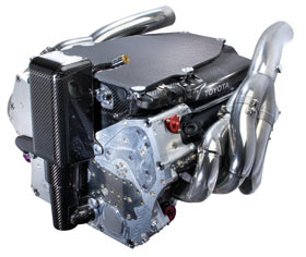
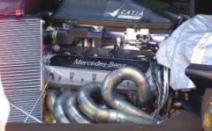
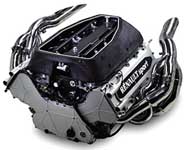
 
V Type Engines 


The V-type of engine has two rows of cylinders set normally at a ninety degree angle to each other. Advantages include it's short length, great rigidity of the block, its heavy crankshaft, and attractive low profile. This is a tried and tested engine design with huge performance potential.
In sports applications, having the engine as low to the floor as possible increases the car's handling characteristics, as it will naturally have a lower centre of gravity. Also having a strong engine with built in rigidity can mean the difference in endurance races, making the V type engine design an ideal choice for Motorsport applications.

With this type of engine it is possible to have a very high compression ratios, without block distortion under load.

This makes it a strong and robust design for high performance applications and is used in F1 for instance. Also with it's resistance to torsional vibration, the engine characteristics produce a smooth and refined engine.
Another attribute for this compact engine design is a shorter car length without losing passenger room. In 1914, Cadillac was the first company in the United States to use a V-8 engine in its cars. From there America has fallen in love with the V type engine and the 50's and 60's produced some of the best Muscle cars.

Boxer/ Flat Engines


In 1896, Karl Benz invented the first internal combustion engine with it's horizontally opposed pistons. This Boxer/Flat engine is an design with multiple pistons that all move in the horizontal plane. The most popular and significant layout has cylinders arranged in two banks on either side of a single crankshaft, generally known as "boxers". This is because the two pistons join together in the middle of TDC ( Top Dead Centre).
This is similar to two boxers touching gloves at the beginning of a bout and is the origins of the name appointed to the engine design.

Flat engines have a lower center of gravity than any other common configuration, so vehicles using them should benefit from better stability and control during cornering. But they are also wider than more traditional configurations and the extra width causes problems fitting the engine into the engine bay of a front-engined car. Subaru have been producing AWD front engined cars for some time now, so where there's a will they is a way.

Boxer engines are one of only three cylinder layouts that have a natural dynamic balance; the others being the Straight/Inline 6 cylinder and the V12 design. This makes for a smooth and harmonious engine at idle.

Boxer/Flat engines tend to be nosier then other designs due to the lack of airboxes and other components in the engine bay. They have a engine characteristic of smoothness throughout the rev range and when combined with a mounting position immediately ahead of the rear axle, offer a low center of gravity and largely neutral handling characteristics.

Wankel/ Rotary Engines


The Rotary Wankel engine was an early type of internal-combustion engine in which the crankshaft remained stationary and the entire cylinder block rotated around it.
The Rotary/ Wankel engine has no pistons, it uses rotors instead. This engine is small, compact and has a curved, oblong inner shape. Its central rotor turns in one direction only, but it produces all four OTTO strokes (intake, compression, power and exhaust) effectively.
 
The only production car to still have a Rotary/ Wankel engine design in production today is the Masda RX-8 and previous RX-7 models.

The Rotary/ Wankel engine is limited by its inherent restriction on breathing capacity due to the need for the fuel/air mixture to be aspirated through the hollow crankshaft and crankcase, which directly affected its volumetric efficiency, also low torque levels are a known problem and the engine has design limitations. Turbocharging this engine is one of the easiest ways around these deficiencies and was seen in the RX-7.

The rotational forces of the mass of the Rotary/ Wankel engine's weight produce a powerful gyroscopic flywheel effect. This smooths out the power delivery and reduces vibration. Vibration had been such a serious problem on conventional piston engines that heavy flywheels had to be added to the overall engine design to help counteract the effects.

The cylinders themselves functioned as a flywheel, Rotary engines gained a substantial power-to-weight ratio advantage over more conventional engines. Another advantage was improved cooling, as the rotating cylinder block created its own fast-moving airflow, even at standstill.
Dispensing with separate cylinders, pistons, valves and crankshaft, the rotary engine applies power directly to the transmission. It's construction allows it to provide the power of a conventional engine that is twice its size and weight and that has twice as many parts.
The Rotary/ Wankel burns as much as 20% more fuel than the conventional engine and is potentially a higher polluter, but its small size allows the addition of emission-control parts more conveniently than does the piston engine.
 
The basic unit of the rotary engine is a large combustion chamber in the form of a pinched oval. Within this chamber all four functions of a piston take place simultaneously in the three pockets that are formed between the rotor and the chamber wall. Just as the addition of cylinders increases the horsepower of a piston-powered engine, so the addition of combustion chambers increases the power of a rotary engine. Larger cars may eventually use rotaries with three or four rotors.

Mazda have had numerous success with this design, especially with the RX-7 and RX-8 models. By adding a turbocharger as discussed previously, the torque deficiencies are some what over come and also  engine power greatly increased. This combined with the lower weight made a effective and competitive performance package. 
   
Diesel Engines


The Diesel engine was first invented by Rudolf Diesel, of German ethnicity born in Paris. Although quite similar in design to petrol internal combustion engines, Diesel engines use compression to ignite the compressed fuel to air mixture prior to injecting it into the combustion chamber, with out the need for spark plugs.

Advantages over Petrol Engines:
  • 45% efficiency in converting fuel into mechanical energy compared to Petrol at 30%.
  • Engine life expectancy is twice as long compared to petrol engines, due to the stronger internal design to cope with higher pressures under combustion.
  • No need for HT leads, spark plugs and coils, meaning greater reliability especially in damp environments.
  • Diesel engines are immune to vapour lock and the fuel is not explosive like petrol.
  • No proportionate decrease in fuel efficiency compared to petrol engines, at higher engine loads.
  • Produce less heat in cooling and exhaust.
  • Produce less carbon monoxide and can be used in underground applications.
  • Can accept turbo/supercharging with out risk of detonation, unlike petrol engines at higher pressure levels.
  • Higher torque lower in the rev range.
  • Diesel fuel is denser then petrol and contains roughly 15% more energy.


Disadvantages over Petrol Engines:

  • Lower power to weight ratio then petrol engines, due to the increased internal component strength.
  • Lower power and rev band range compared to petrol engines, although turbo/ super charging has helped to combat this in the last decade.
  • Normally noisier and rougher in operation compared to petrol counter parts, although diesels are almost on par with technological advancements.
  • More expensive to purchase and run compared to petrol alternatives, due to increase in stronger components and more regular service schedules.

Pages: [1] 2 3 ... 6